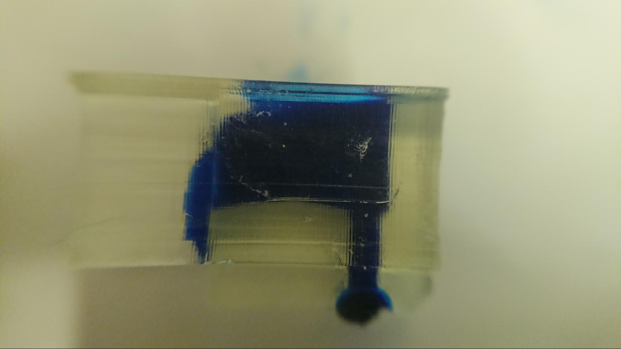
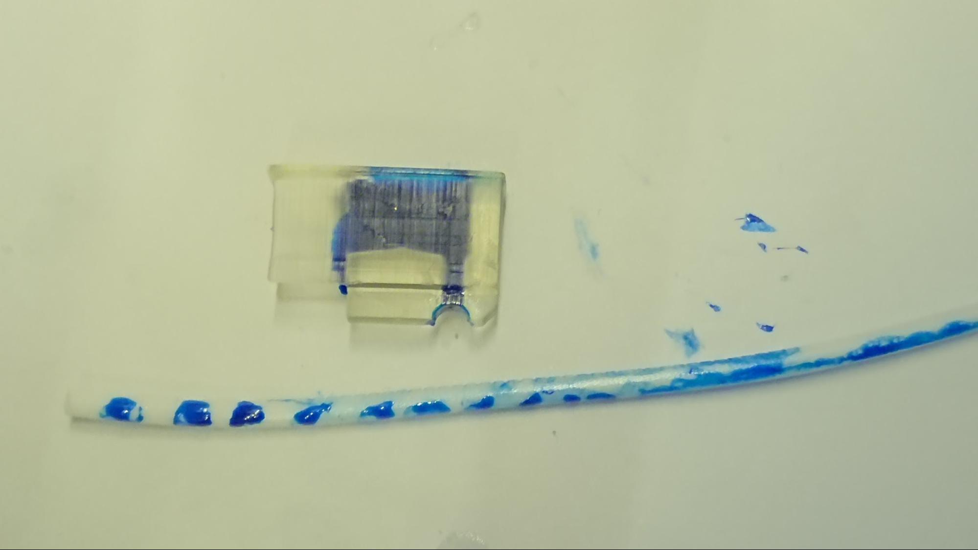
Full color 3D printing on fused deposition modeling printer with filament coloring addition mechanic and controlling algorithm
Developed in 2016-2017
Product Development Name: Single Extruder Fused Deposition Modeling 3D Printers Full Color Ink Cartridge System
Mission
Current Fused deposition modeling (FDM) 3D printers have only one way to achieve full color 3D printing. By blending multiple filament with different color into a single hot end to mix color within the hot end and create multi color printing. However, this method require multiple extruders (i.e. Stepper Motors) which will significantly increase the cost of the machine as the increased number of extruder lead to more complicated electronics and require special software support. Inspired by the traditional office printer, a new concept that make use of only one color of filament as “paper”, and liquid pigment as “ink” had come up. This development project may revolutionize the current home use 3D printer industry as cost is one of the main factor for home use 3D printers popularization and bring home use 3D printers into the age of full color printing.
This system require a highly accurate and state of the art controlling algorithm in order to apply the correct color at the correct timing. Thus, in this report, the methods of system control and mechanical design will be explained.
Aim and Description
This system was designed for adding color (Oil based paint) directly onto the printing filament (usually in white or transparent) before the filament enter the 3D printer extruder. Hence, by applying a calculated pattern of color dots based on CMYK color scheme onto the filament and feed it into the 3D printer hot end to perform color mixing, a full color 3D printed object can be created.
This project mainly focus on the proof of concept over pre-colored 3D printing methods compare to the existing “Mix on printing” and “Paint after print” methods.
Applications
This system are design to fit all FDM printer that is designed based on Reprap open source project. (Include but not limited to “Reprap prusa i3”, “Reprap Delta”, “Reprap Prusa i3 Rework”, etc)
Or other 3D printers with the following specification:
Hot End Temperature | >200 Degree Celsius |
Filament Diameter | 1.75mm (1.70mm - 1.80mm) |
Hot End Type | E3Dv5 / E3Dv6 / Some Ultimaker Machine (Theoretically workable) |
Marketing Analysis and Planning
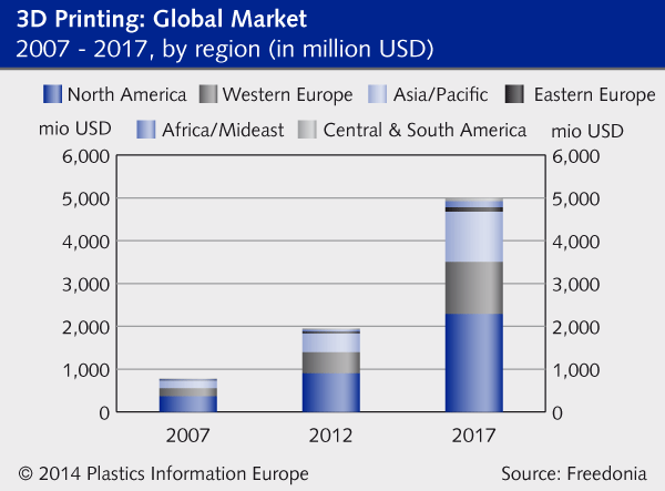
“Prototyping will remain the largest application but stronger growth will come from production and consumer uses as 3D printers will increasingly be used to manufacture direct production parts and finished goods. Some of the fastest growth will be seen in the medical and dental sectors, while other significant markets include consumer products such as jewellery, toys, fashion clothing and electronics as well as automotive and aerospace. Pauline Tung, an analyst with Freedonia, expects “greater adoption of additive manufacturing technologies as 3D printing speeds and material quality improve” .“
By Plasteurope.com
On Kickstarter (One of the most famous crowdfunding website in the world), there are 495 projects that related to 3D printing, some of them raise fund up to 3.4 million USD.
Hence, we can see there is a great market on 3D printers, and this machine is a complement of 3D printers. We can expect its demand will have similar effect to the 3D printers during the 3D printing trends.
Build Process
Initial Design
Mechanical parts
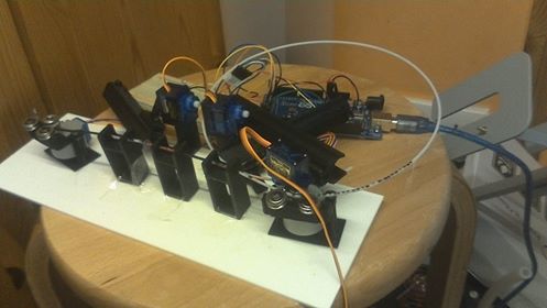
Experimental Build 1st Version in Summer of 2016 Development Failed due to slow response time of 9g Servos and not enough torque of 4V stepper motors Project redesigned and improved by using DC electromagnet solenoid and 48 Steps 12V Stepper Motors (Same as the one used in most 3D printer as Extruder) | |
1st Prototype 2nd Version in Sep, 2016 The use of elastic bands are able to increase the retract time of the DC electromagnetic solenoid (piston) and perform more accurate color addition to the filament. However, the friction between the paint holder are too large, some of the piston cannot be pushed smoothly lead to an voltage peak back into the microcontroller, affecting the servos nearby. Improvement: Remove servos, and align all the piston in a linear format to reduce friction between each unit. (For the design sketch of this base, please refer to the Appendix A1, A2 and A3) | |
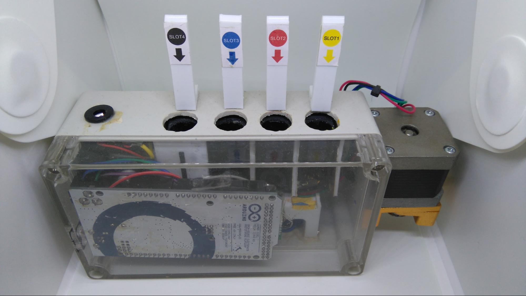
Success Prototype 3rd Version in Oct,2016 This prototype was succeeded with Arduino Mega as controller and able to create the first Full Color printed object with Color Addition Method based FDM 3D printer. |
Electrical parts (Controller Board)
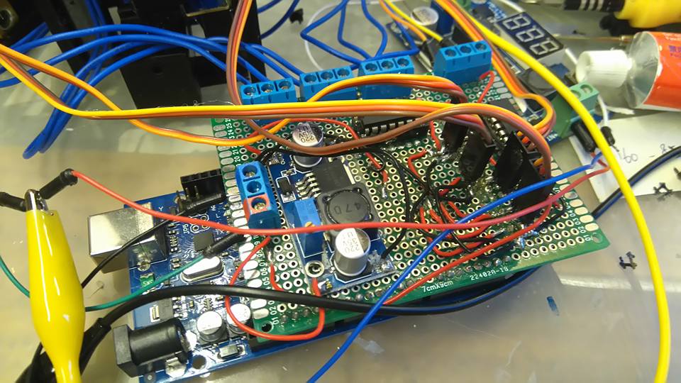
Experimental Build Electromagnetic solenoid and servo control system (ESSC System) was built for initial testing and experimental purpose. However, this development board is too big to be included into the casing of the later design. | |
1st Prototype This ESSC prototype was designed to be included inside the casing of the final prototype. However, part of this prototype was damaged during testing, and the whole board was redesigned. (For pin layouts, please refer to Appendix A4) | |
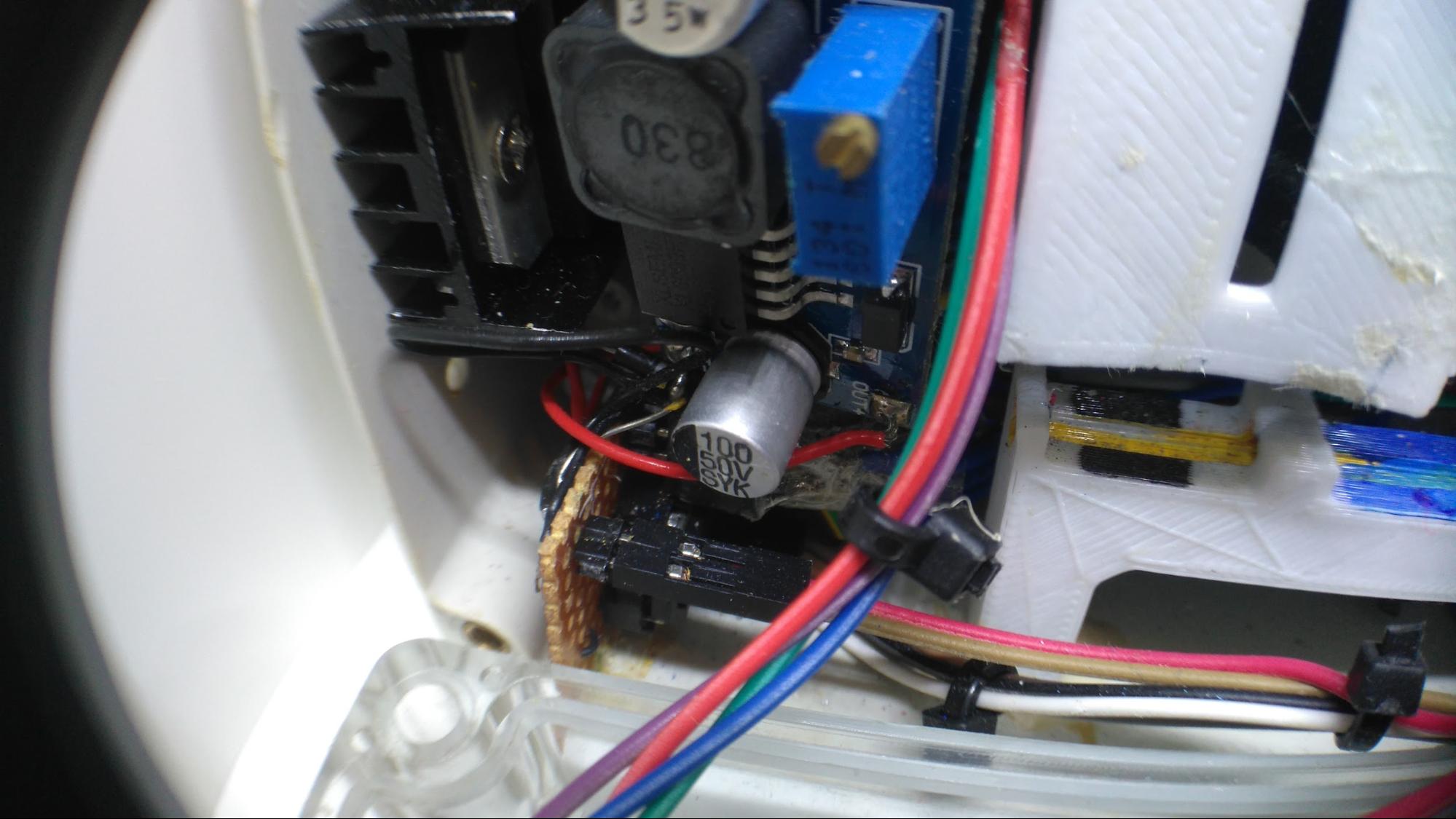
Success Prototype The finalized ESSC system was included onto a tiny board on the left side of the picture (The little brown circuit board below the black heat sink) And part of the function of the original board was separated to the 2 modules for handling the voltage regulation and power supply for the electromagnetic solenoid and sensitive electronic like the microcontroller. This machine required an input of 12V, and its internal buck converter will step down the voltage to 5v and boost convertor to step the voltage up to 24V for different part of the machine to operate at normal voltage. (For extruder design, please refer to Appendix A5) |
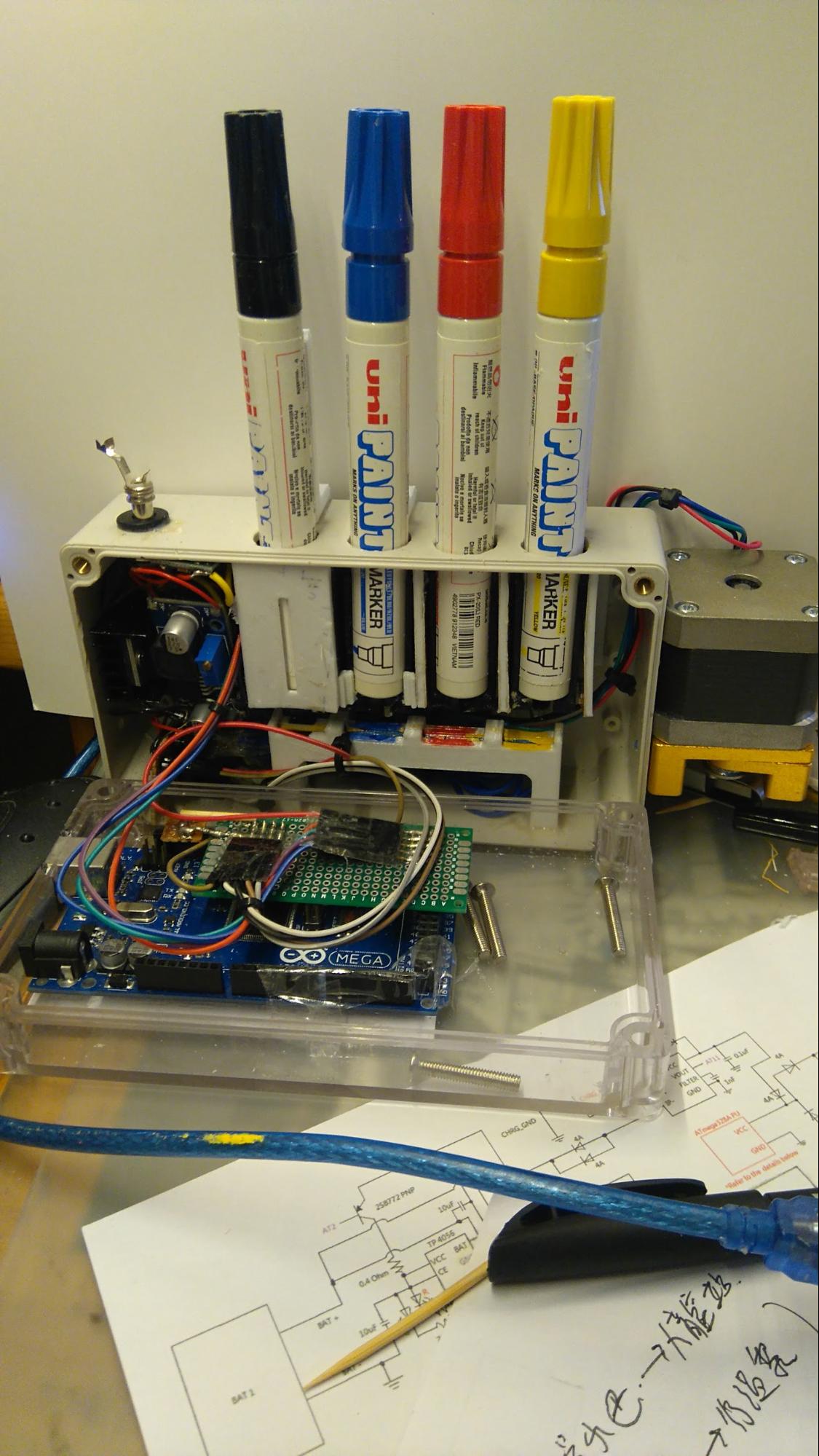
Electronic System (Left) and Color Application System (Right)
Electric Solenoid in Linear (Metal parts above the coloring tunnels)
Coloring Tunnels which inks drop on top of the filaments
Operations
The ink cartridge used was designed to fit open source design, hence, the UNI PAINT Marker was used as it can be easily found in stationery shops all around the world. To start the ink application process, the first action was to insert the PAINT Marker into suitable slot and perform leveling for the electromagnetic solenoid (This step only require once at startup process)
< This picture is only for reference. As the PAINT Marker are easily dried off after opening the pen cover, this picture was taken with the pen upside down and not opening the pen case. |
The main microcontroller is Arduino Mega 2560 which is an open source Atmel AVR based Development Board you can easily find around the world. Hence, this system can be operated via USB Serial Convertor and control on your laptop. During the first stage of development, a direct driver interface was created for initial testing.
By entering the coloring sequence based on CMYK, the software can drive the devices directly via serial and create a filament with correct coloring array.
Advanced Coloring Algorithm
A control software was developed for this project, named as “Vertex Painter”.
The exported gcode from Cura was converted into point cloud (i.e. remove all extra information and only extract the x y z data). The processed data was imported into Vertex Painter for the user to paint each vertex in RGB color format. The following picture was a point cloud of teapot for demo.
The system also contains another python code file for converting the gcode into extruder value (Assume to gcode use the command G21, then the unit of the extruder value is in mm). Lastly, a python script “Coordinate2Array.py” combine the extruder data and the color data into a txt file, which list all the color that is needed to apply to the filament for further processing.
The exported txt file can be filled into the program above manually and apply color to the filament.
Experimental Result
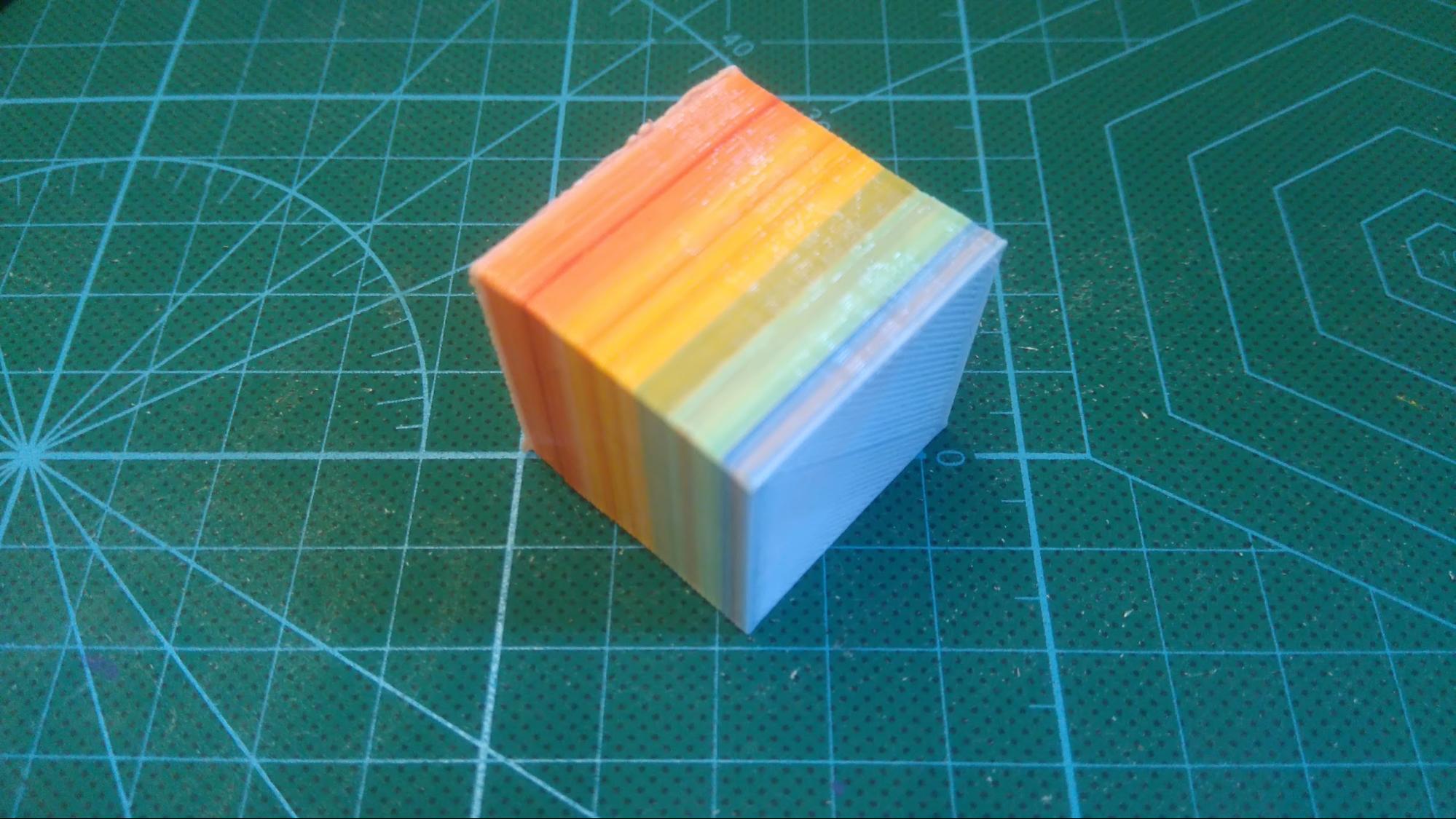
1. Experiment to generate a piece of purple filament using Blue and Red as the color source.
The filament was generated successfully with a distance separating the darker color(blue) and lighter color (red) to prevent the blue ink contaminate the red pen tip.
2. Experiment with a dotted white PLA with the following configuration
(The right side of the filament will be the lower layer and the left side of the filament will be the upper layer)
Result as follow.
Experiment with all color range
In this part, an array of color data was sent to the machine. For simplicity, R = Red, Y = Yellow, B = Blue and K = Black
{R,R,R,R,Y,R,Y,Y,Y,Y,B,Y,B,B,B,B,B,R,B,R}
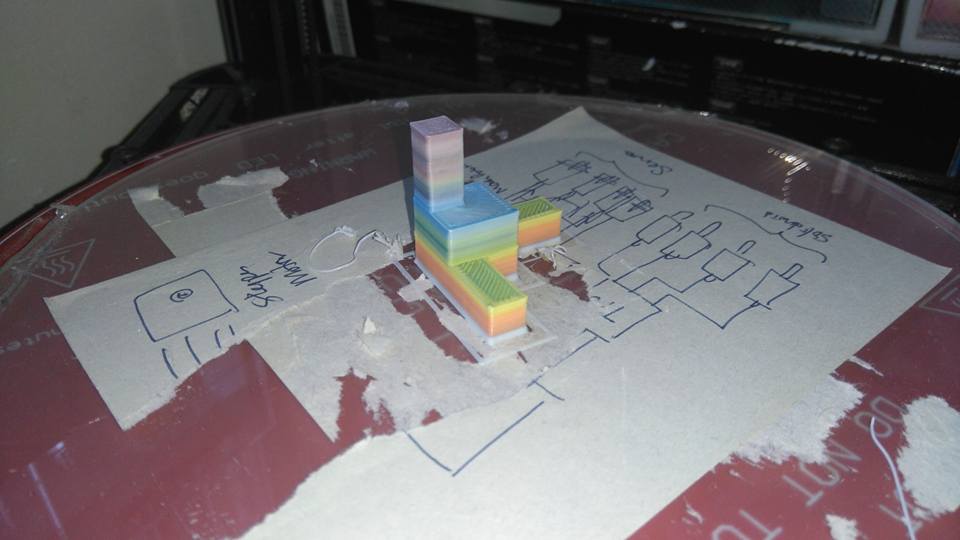
The following result was given out
Weakness and Further Research
Color Accuracy
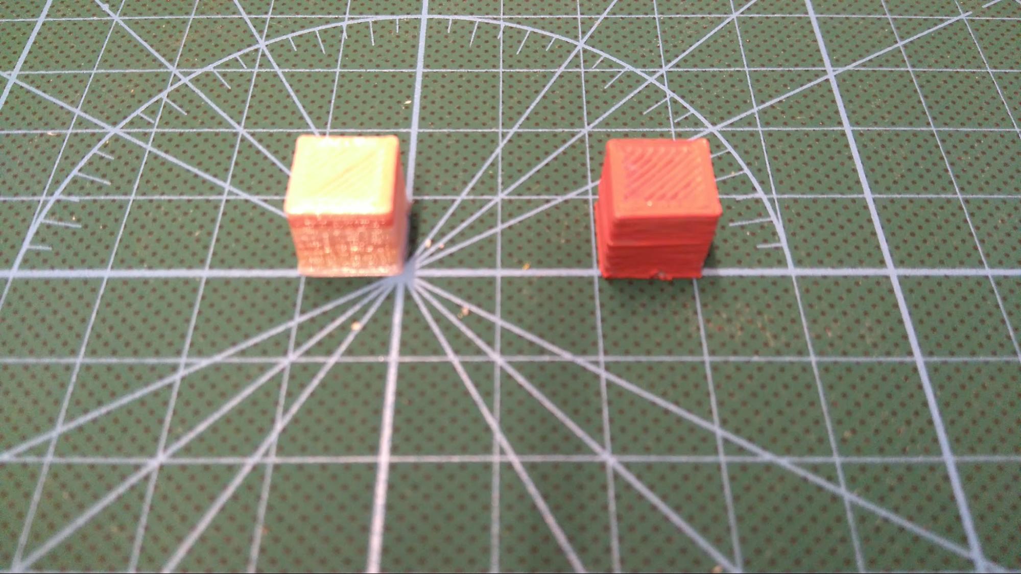
The following image is two cube with a volume of 1 cm^3.
The right one was painted with oil based paint.
The left one was printed using the same oil based paint as color source.
The color intensity has significant different from the paint itself.
3D printed with color addition method (Color Code: #CD8C6C) | Painted after 3D printed (Color Code: #FF9196) |
Expected Solution
Research in color application has to be done in order to find the correct adjusted CMYK value for this color addition methods.
Wasted PLA filament during initialization of coloring process
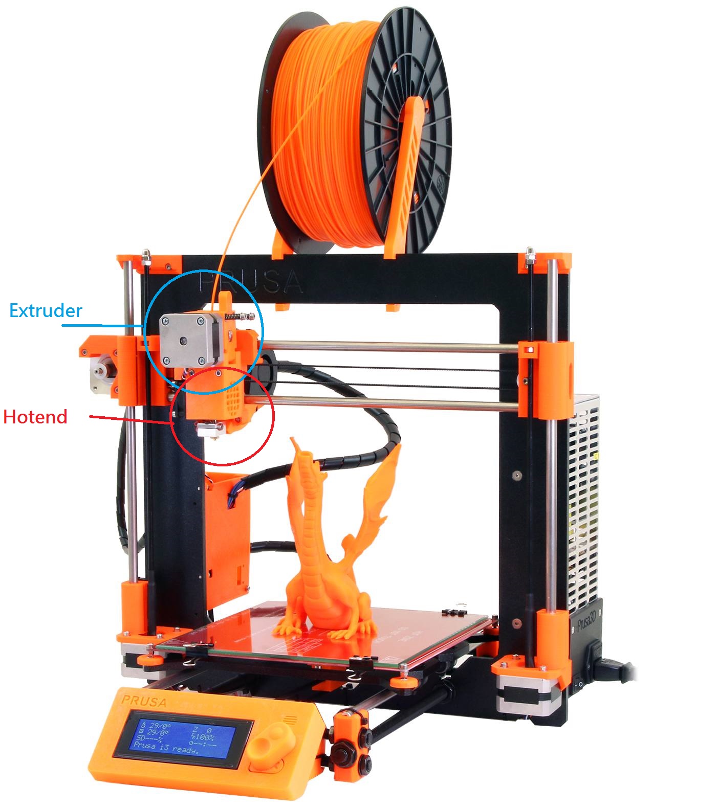
The filament coloring addition mechanic perform color addition task before the extruder. Due to the distance between the extruder and hotend are relatively far for most of the 3D printers (there are exception like pursa i3 in which the extruder is placed directly above the hotend ), there are a certain amount of filament was wasted during the color initialization process as the non-colored filament have to be removed before the first coloring array dot reached the hotend. The demo picture below shows the effect with a standard RepRap Delta 3D printer.
Expected Solution
A new kind of ink cartridge will be developed instead of using PAINT MARKER as the ink source. Thus, a new system will be developed and used directly above the hotends (i.e. The new system are meant to be placed between extruder and hotend). However, it is too expensive to develop a new ink cartridge as the viscosity of oil based paint is different from normal inkjet printer. Hence, the new design was not included in this report.
Version In Development
A new miniature modular version of the color addition machine is currently in development. The new version will use a variable voltage divider as input to control the frequency of color array application.
Appendix (I)
Please be noted that these designs in appendix is copyrighted before the owner of these designs publish this project as open source.
A1
Multi Angle Color Addition System Base Holder
A2
Multi Angle Color Addition System Base Holder Parts Position
A3
Multi Angle Color Addition System Base Holder Color PLA RAW Material passing tube
(The design of this tube were same in both 2nd Prototype and Succeeded Prototype)
A4
2nd Prototype ESSC System Pin Layout Diagram (Arduino Mega / Atmega2560 Corresponding pins with Arduino Bootloader)
A5
Extruder Design Draft
(The raspberry pi system was not used to reduce cost, also, the PLA empty detection was removed as the filament will not exit on the upper part of the devices)
A6
All the mechanical parts that perform the action of ink application. Printed with PLA or ABS with FDM printer.
A7
Inkwell Setup Example
Single Extruder Fused Deposition Modeling 3D Printers Full Color Ink Cartridge System
Development Stage 2
Furicas Project (FUll coloR Ink CArtridge System)
Simplified Diagrams
[This devices can be placed between the filament and the hotend. Custom software will control the application of color dots array and create the suitable color pattern to create the desired output color. The color of the final product can be calibrated using standard RGB sensor module with arduino, send back to the software and apply adjustment to improve the next print. (Work in progress)]
[In simple words, a normal home 3D printer with the filament color application devices can create full color 3D printed object with much lower cost than industrial or multi extruder machines.]
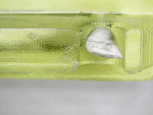
InkWell color application process under microscope
- The pigment market tip contact with the PLA filament
- The liquid pigment wrap the whole section of filament due to capillary motion.
- The pen tip retract back to its resting position, the ink then let dry inside the devices.
- Next section of filament will be shifted into this inkwell and repeat the color application process.
Color application and 3D vertices reconstruction accuracy
Color Application Accuracy
[The CAA was shown in the above graph. Color offsets of Cyan is due to the chemical properties of blue pigment. Majority of blue pigment will cause color degrade problem during the heating and cooling process within the Hotend. This problem is expected to be solved with custom made pigment in the future development. ]
[CAA measurement using 120x electronic microscope. Samples printed with layer height = 0.3mm. CMYK value was calculated after averaging the whole captured image.]
Vertice Coordinate Accuracy
The accuracy of asc generated is depended on the gcode generating software. In this example, Cura was used to generate the gcode for further processing into asc. Each vertex shown in the asc file can be painted and represented one color dot.
[Example stl file] | [Processed asc file] |
Example Cube with custom written software and filament color application devices
Exhibition Poster (Left)
Exhibition Poster (Right)
Version 5 - Black Gradient Control Unit
This version of the Furicas are designed to control only black paint. Hence, the gradient of the colored filament can be further adjusted.
The custom made micro controller unit (Tinduino) are used to generate time delay for each color array application using the value of the adjustable resistor’s voltage.
Internal structure of this version as shown in the picture on the left. The Tinduino custom made AVR microcontroller development board controls a darlington transistor array. The array are used to control the linear electron solenoid to move the pen carrier with the piston. This design is similar to a single unit of the original version 4. Except it can be used stand alone without the need of computer control. |
Development Stage 3
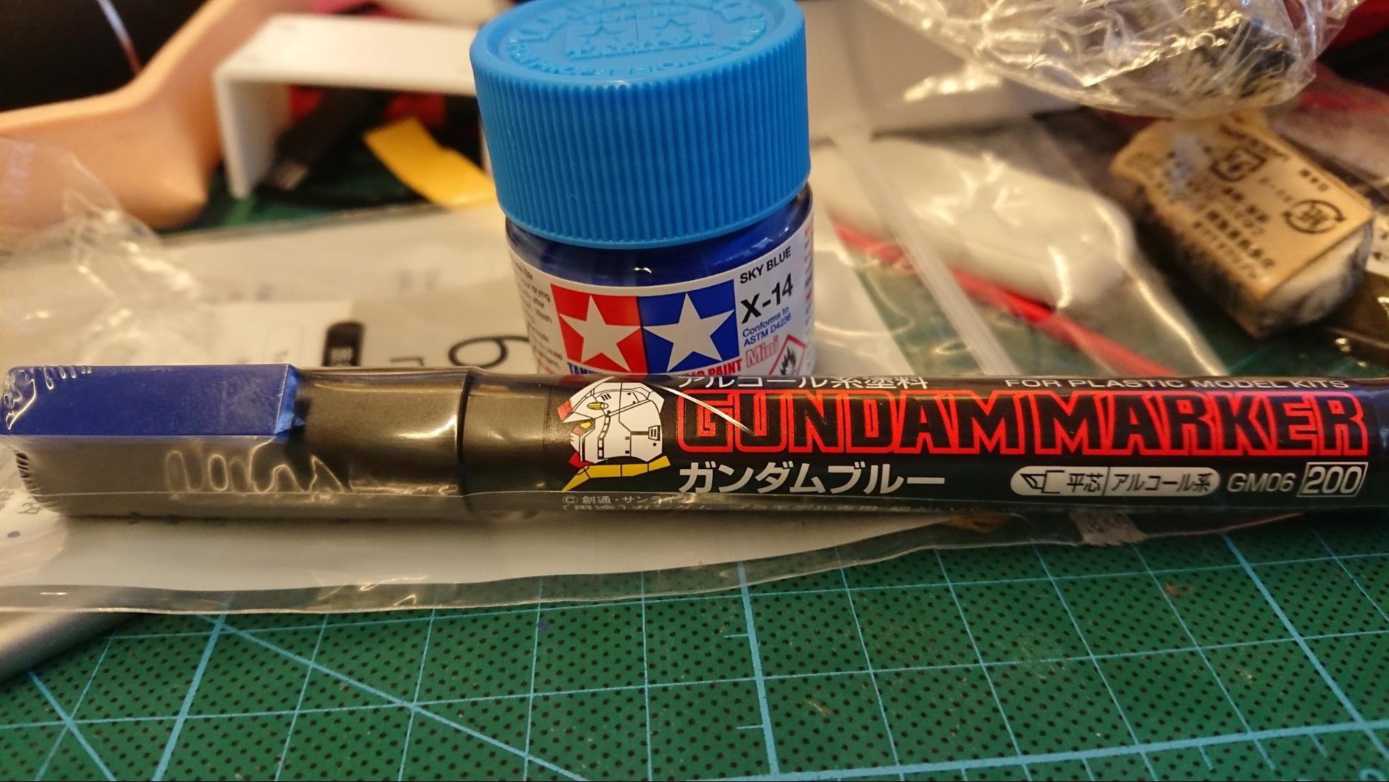
Alternative solution to UNI PAINT MARKER
Experimental Coloring Agent
|
Experimental Result
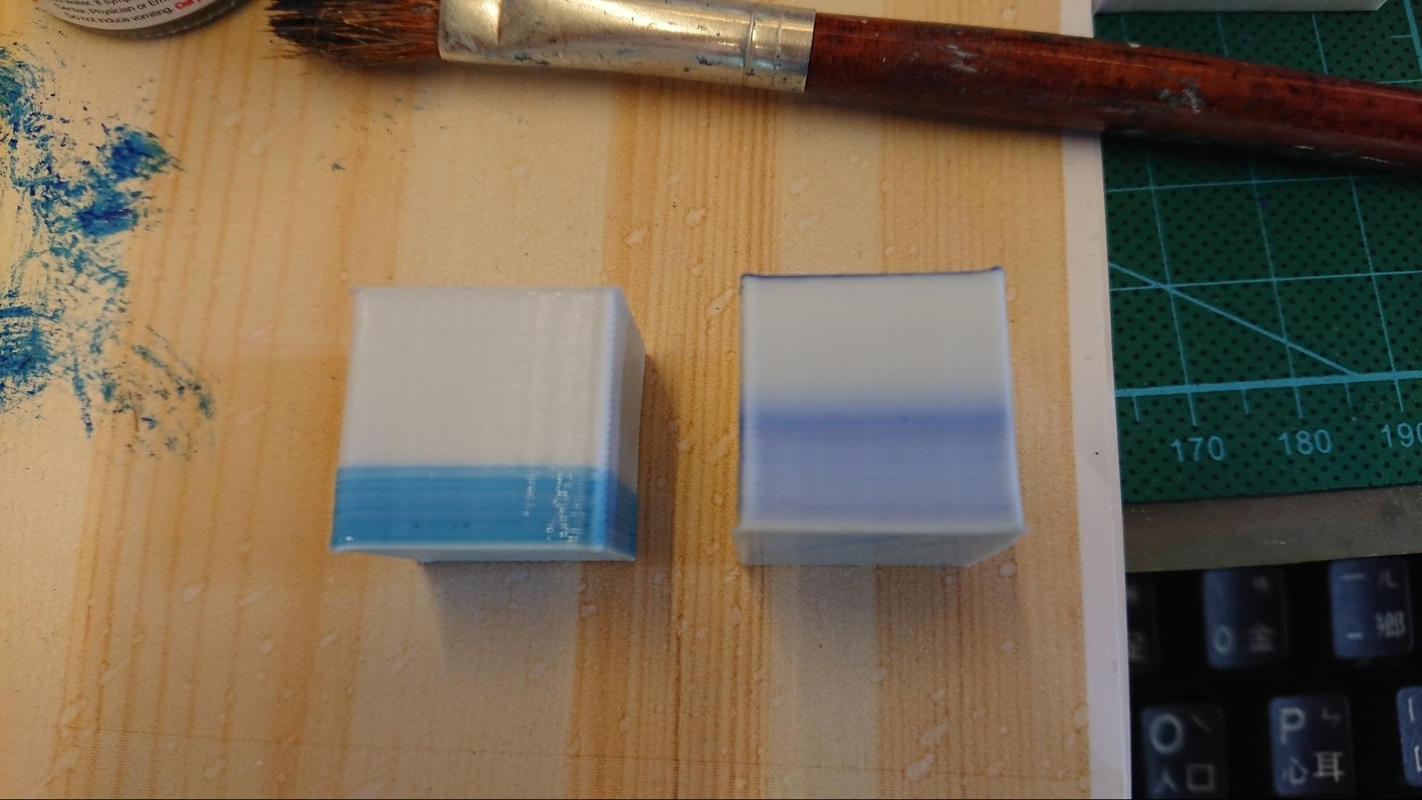
Print with White PLA at 215 Degree Celsius. Left one is the print with TAMIYA COLOR, right one is the print with GUNDAMMARKER. With the target of recreating Cyan (#00B7EB, subtractive primary) after the heating and color loss process.
Analysis
- The concentrated solution work great to reduce color losses during the heating process.
- All side of the PLA filament has to be painted with pigment in order to produce same color gradient on all side of the print.
Color Application System Design
As the source of pigment has been updated from UNI PAINT to TAMIYA COLOR (TC Paint) oil based paint, the color application system design has to be updated in order to maximize the advantage of the new painting pigment. The design was as follow:
Top left view of the ink application jet head There are two side with curved edge to prevent ink from entering another jet head and blocking / mix with other colors ink. The opening of each ink ejection port are in 1 mm * 1 mm to provide a small enough space for water surface tension to hold the fluid within 0.3mm of the opening of the jet head. | |
The side view of the jet head. Each ink ejection hole are separated with a gap of 2 mm with 2 mm radius shield for leading the fluid slide over the side of the PLA and increase the surface area of paint application. |
Working Principle
(Represented using the 2nd version of Jet Head Prototype)
1st Jet Head Prototype
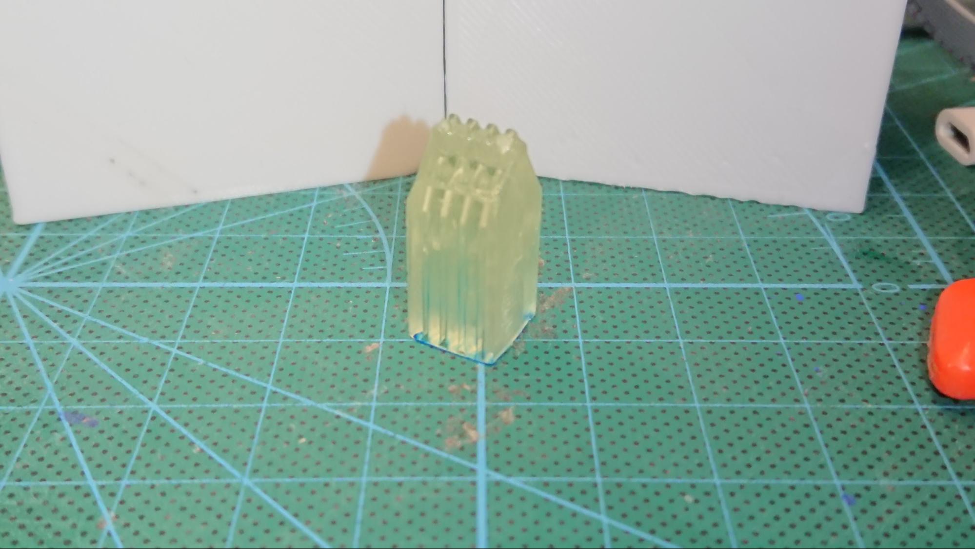
The 1st Jet Head Prototype failed due to the UV sensitive resin has blocked the 1mm jet head and during the UV curing process, the head got clogged and not able to eject any fluid.
2nd Jet Head Prototype
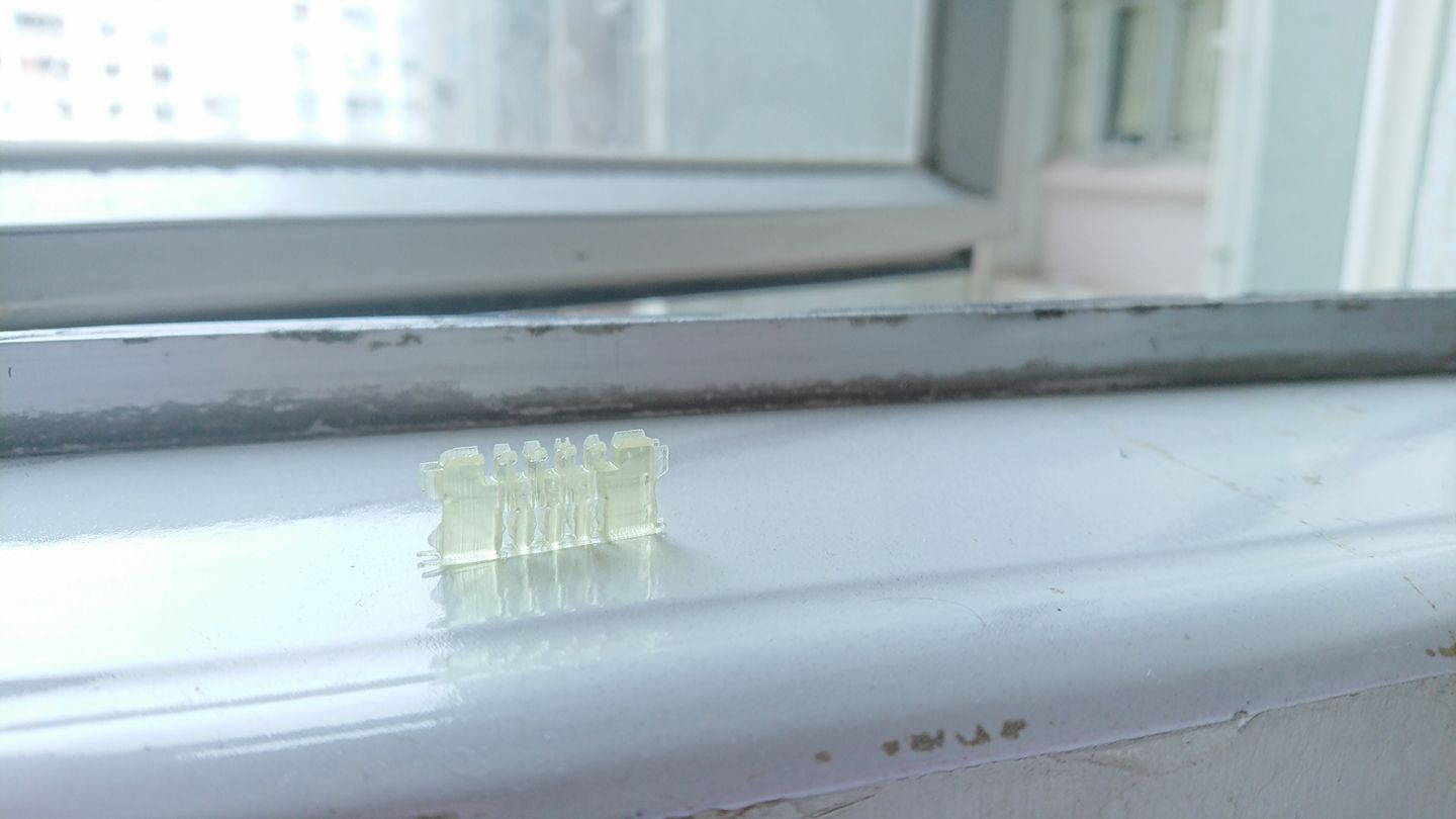
The 2nd prototype face similar problem as the first prototype and the jet head was clogged during the curing process. However, two of the four ejection hole did work normally and the TC paint was inject into the unit using syringe. However, due to the pressure of ink inject, the ink overflow from the jet head ejection hole and stick to other holes due to capalar motion.
The distance between each holes are proposed for increasing into 5 mm. And the walls between each ink jet head buffer zone are proposed for increasing from 1mm to 3mm.
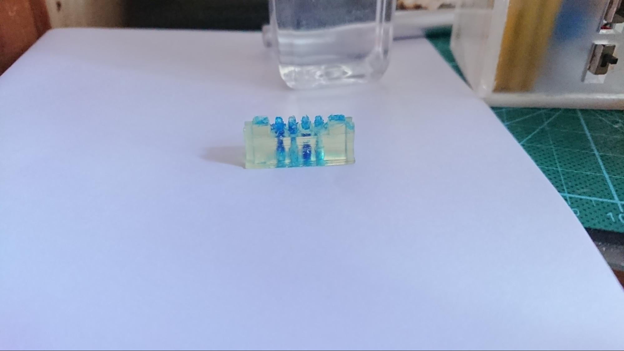
- The ink was injected into the ink head from the nozzle. The ink successfully stick to the inner wall of the head and the surface tension can create an ink drop at the opening of the nozzle
- The nozzle has to installed further to each other to prevent the capalar motion overriding the surface tension.
3rd Jet Head Prototype
This version was printed successfully on the DLP 3D printer as its Ink Tunnel walls are too thin. Hence, leakage occurs at the pressure enhancement structure. Version 4 will improve the design and thicken all the wall in the Jet Head structure. |
4th & 5th Jed head Prototype
The 4th Version of the prototype cannot fix the problem of over thinning wall in the previous version 3. Hence, the 5th version was an enhancement over the 4th version with thicken walls and nozzle.
The result of the V5 as shown in the picture on the left. The structure was created perfectly with no color migrate onto the other color nozzle and the ink was hold in place by surface tension. By pressing the filament onto the PLA slot, the color dot was added onto the filament successfully. However, this design cannot apply more than one color. |
6th Prototype (Single Slot)
Version 6 has splitted the 4 color required into 4 different slot. Each slot has the same design for easy printing. The back of the slot include a 3mm wide controller adapter for servo attachment.
4 of the Jet Head can be aligned in this format for full color application control that add color array dots onto the filament.
Experimental Result of v6
The Prototype Version 6 was printed and inserted a string of APP fiber (Also known as “tissue fiber”)
The following configuration shows the APP fiber is connected to the nozzle and the base of the ink buffer.
During the ink filling process, the backside of the ink buffer leaked due to over thinned wall. As shown in the image below.
The test color array on the PLA filament was succeed and created an even pattern on the top side of the filament. (The left part was printed with Prototype v6, the right part was printed by v5)
Visualization of Ink Jet Nozzle Unit
Pseudocode for color application array (Embedded AVR C++)
Int Current Position;
Int Unit Length;
Int n; // In stepper motor steps
For each color_dot in color_array{
Move_To_Nozzle(color_dot);
Apply_color(color_dot);
Move_Steps(n); //n = software correction value for the next color dot
Print(debug_message);
}
Standalone controller with Web Interface
- The esp8266 module was used instead of the Arduino MEGA to provide Wifi access command to the system.
- The esp8266 module was controlled by an custom written module based on ArOZ Online BETA for quick access and easy integration with home automation system.
- The system will be controlled by command mode instead of local storage mode. (Color data are sent while request instead of downloading and running) to provide real time modification and termination.
- Raspberry pi will be used as the host of the control system.
Copyright Toby Chui
All right reserved except specified resources.
Last update: 18/8/2017

